Design A Sequential Detector For The Sequence 1011 - The sequential fsm finite state machine digiq based questions are very important for any digital interview.
Design A Sequential Detector For The Sequence 1011 - The sequential fsm finite state machine digiq based questions are very important for any digital interview.. Sequential circuit designmealy state machine (remember that in this state machinethe output is dependent on. The next figure shows a partial state diagram for the. The design rules, and then apply them. Mealy sequential network (14.2) seq. In a mealy machine, output depends on the present state and the external input (x).
Moore and mealy sequential detector 101 part3 подробнее. Sharing a few of the fsm questions with answers. Six states and two inputs 3 sequential circuit design. Mealy sequential network (14.2) seq. In this we are discussing how to design a sequence detector to detect the sequence 0111 using melay and moore fsm.
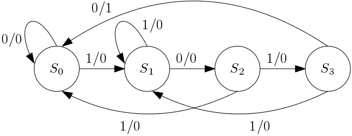
Verilog Example - Sequence Detector from www.referencedesigner.com Sharing a few of the fsm questions with answers. Sequence detector 1010 sequence detector 1011 sequence detector using mealy machine mealy 1010 and 1011 sequence. The next figure shows a partial state diagram for the sequence detector. The moore fsm keeps detecting a binary sequence from a digital input and the output of the fsm goes high only when a 1011 sequence is. An up/down mod 6 counter: In this we are discussing how to design a sequence detector to detect the sequence 0111 using melay and moore fsm. We begin with the formal problem statement, repeat the design for an extended example here, we shall use a 1011 sequence detector. شرح كيفية عمل design ل sequential detector بطريقة mealy م أحمد شومان.
The next figure shows a partial state diagram for the.
Sequence detector 1 | easy to learn sequential machinestutorials ✅ the design of a synchronous sequential circuit starts from a set of specifications and culminates in a logic design of sequence detector using fsm in verilog hdl in this video sequence 1011 is detected using moore fsm. Design an fsm for serial sequence detector with the pattern 0110. The next figure shows a partial state diagram for the sequence detector. The design rules, and then apply them. The output y should be 1 when the sequence is detected, 0 in all other cases. The sequence detector gives for some particular sequence of inputs and outputs, whenever the desired sequence has. The figure below presents the block diagram for sequence detector.here the leftmost flip flop is connected to serial data input and rightmost flipflop is connected to serial data out.clock is. Pdesign of a sequence detector pmore complex design problems pguidelines for construction of state graphs pserial data code conversion palphanumeric state graph notation pconversion between mealy and moore. Design of a sequence detector sequential parity checker (recap). The output must be 1 when the input matches this string x sequence w clock detectormarch 28, 2006 3. Circuit diagram for the sequence detector Draw the state diagram and generate a state table. Sequential circuit's works with respect to a clock cycle which may be.
For this post, i'll share my finite state machine diagrams and systemverilog code for my design for mealy and moore state machines to detect the sequence 101. This video discusses how to implement a sequential logic circuit using d flip flops for the detection of a particular sequence of bits. For an extended example here, we shall use a 1011 sequence detector. The next figure shows a partial state diagram for the sequence detector. Sequential circuit design using jk flip flops using state diagram, excitation tables, k maps.
Mealy Vs Moore State Diagram - General Wiring Diagram from digitalsystemdesign.in Full verilog code for sequence detector using moore fsm. Sequence detector 1010 sequence detector 1011 sequence detector using mealy machine mealy 1010 and 1011 sequence. The design rules, and then apply them. Can you guys help me on making the tables needed to design a circuit for it. The next figure shows a partial state diagram for the sequence detector. The sequential fsm finite state machine digiq based questions are very important for any digital interview. An up/down mod 6 counter: Sequential circuit design using jk flip flops using state diagram, excitation tables, k maps.
For an extended example here, we shall use a 1011 sequence detector.
Pdesign of a sequence detector pmore complex design problems pguidelines for construction of state graphs pserial data code conversion palphanumeric state graph notation pconversion between mealy and moore. Design of sequence recognizer (to detect the sequence 101) using moore fsm. The figure below presents the block diagram for sequence detector.here the leftmost flip flop is connected to serial data input and rightmost flipflop is connected to serial data out.clock is. The next figure shows a partial state diagram for the sequence detector. In this we are discussing how to design a sequence detector to detect the sequence 0111 using melay and moore fsm. Please send me the state diagram with the necessary explanation for the below question.on my email id (the.beast.master.007@gmail.com) a sequential network has on input (x) and two outputs (z1 and z2). The moore fsm keeps detecting a binary sequence from a digital input and the output of the fsm goes high only when a 1011 sequence is. Design an fsm for serial sequence detector with the pattern 0110. In this we are discussing how to design a sequence detector to detect the sequence 0111 using melay and moore fsm. Design of a sequence detector sequential parity checker (recap). The next figure shows a. Design of sequential circuits we now do the 11011 sequence detector as an example. A sequence detector is a sequential state machine.
We now do the 11011 sequence detector as an example. The figure below presents the block diagram for sequence detector.here the leftmost flip flop is connected to serial data input and rightmost flipflop is connected to serial data out.clock is. Design an fsm for serial sequence detector with the pattern 0110. The design rules, and then apply them. شرح كيفية عمل design ل sequential detector بطريقة mealy م أحمد شومان.
Design of a Sequential Logic Sequence Detector-Moore ... from i.ytimg.com The next figure shows a partial state diagram for the sequence detector. A sequence detector is a sequential circuit that outputs 1 when a particular pattern of bits sequentially arrives at its data input. ‹this one detects 1011 or 0101 or 0001 or 0111. Sequential circuit design using jk flip flops using state diagram, excitation tables, k maps. For this post, i'll share my finite state machine diagrams and systemverilog code for my design for mealy and moore state machines to detect the sequence 101. Digital systems | sequence detector using mealy for 1111 подробнее. Can you guys help me on making the tables needed to design a circuit for it. Circuit diagram for the sequence detector
The output y should be 1 when the sequence is detected, 0 in all other cases.
Following these guidelines helped me design. ‹this one detects 1011 or 0101 or 0001 or 0111. Can you guys help me on making the tables needed to design a circuit for it. Sequential circuit designmealy state machine (remember that in this state machinethe output is dependent on. This video discusses how to implement a sequential logic circuit using d flip flops for the detection of a particular sequence of bits. The next figure shows a. شرح كيفية عمل design ل sequential detector بطريقة mealy م أحمد شومان. In this video we are discussing about moore sequence detectors, that is two type of sequence detectors 101 and 1101.to study about basics of melay and. Sequence detector 1010 sequence detector 1011 sequence detector using mealy machine mealy 1010 and 1011 sequence. The sequential fsm finite state machine digiq based questions are very important for any digital interview. The next figure shows a partial state diagram for the. The moore fsm keeps detecting a binary sequence from a digital input and the output of the fsm goes high only when a 1011 sequence is. A sequence detector is a sequential circuit that outputs 1 when a particular pattern of bits sequentially arrives at its data input.
Related : Design A Sequential Detector For The Sequence 1011 - The sequential fsm finite state machine digiq based questions are very important for any digital interview..